自作・実験工程のメモとして
20.Mar.2019
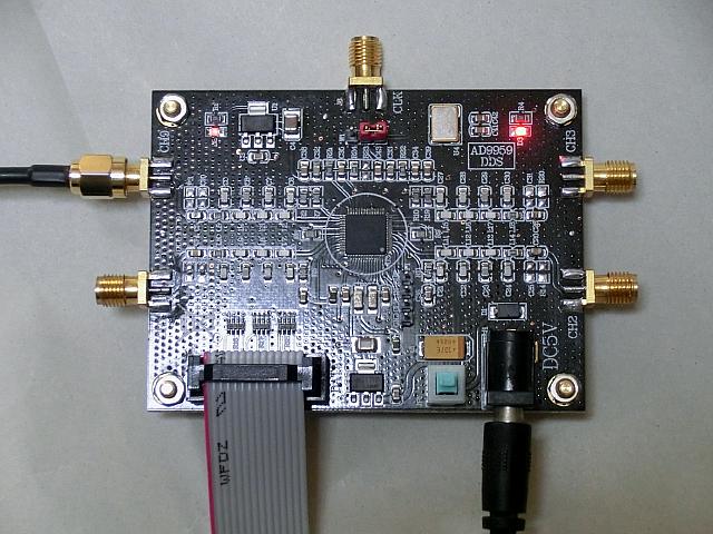
![]() STM32F103でAD9959を動かす
STM32F103でAD9959を動かす
自作・実験工程のメモとして
20.Mar.2019
Edit by bluegriffon3.0.1
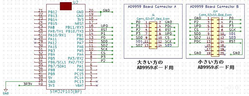
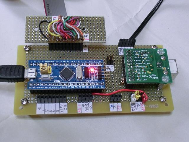
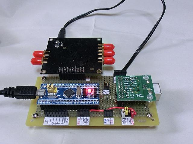
| 1.STM32F103(Blue Pill)周辺の回路 |
| 2.発振出力が出るだけの簡易スケッチ |
| /* 2019/03/18: STM32F103でAD9959を操作するスケッチ 発振周波数は20MHz。 この最小構成で発振する。 Phaseをwhole4に名称変更(2019/03/23) */ #define LED_PIN PC13 // PC13 or 32 or D32 // ============================================== // AD9959 Board I/F ピンの定義 #define AD_UPD PB11 // I/O UPDATE(out) #define AD_SCK PA5 // SCLK(out) SPI:SCK #define AD_CS PA4 // Chip Select Active Low(out) #define AD_IO0 PA7 // Serial DATA Pin(in/out) SPI:MOSI #define AD_IO2 PA6 // Serial DATA Pin(in/out) SPI:MISO #define AD_RST PB10 // Reset(out) // AD9959 レジスタ・アドレス #define CSR_AD 0x00 #define FR1_AD 0x01 #define FR2_AD 0x02 #define CFR_AD 0x03 #define CFTW0_AD 0x04 #define CPOW0_AD 0x05 #define ACR_AD 0x06 // ============================================== #include <SPI.h> // ============================================== // AD9959 インストラクション命令関数のプロトタイプ宣言 void io_update( uint16_t ); // I/O UP-DATE (uint16_t = uS ) void reg7set(byte, byte); void reg15set(byte, byte, byte); void reg23set(byte, byte, byte, byte); void reg31set(byte, byte, byte, byte, byte ); // ============================================== static union { // 共用体 uint32_t whole4; // 32bit byte inByte[4]; // 4Byte } uniD; double dCalFtmp; // ( = 8.589934592 x Frequency) long lCalFtmp; // Long (4Byte)integer const double M859 = (8.5899346 + 0.0000363); // For frequency fine adjustment void setup() { pinMode(LED_PIN, OUTPUT); digitalWrite(LED_PIN, HIGH); // LEDはHIGHで消灯 // ============================================== // AD9959 Board I/F Pin Configuration pinMode(AD_UPD, OUTPUT); pinMode(AD_CS, OUTPUT); pinMode(AD_IO2, INPUT); // とりあえずINPUT(floating)とする pinMode(AD_RST, OUTPUT); // ============================================== // SPI Configuration SPI.begin(); // SPI1ポート オン SPI.setBitOrder(MSBFIRST); // ビットオーダーの設定 SPI.setDataMode(SPI_MODE0); // データモードの設定 SPI.setDataSize(DATA_SIZE_8BIT); // データサイズの設定 SPI.setClockDivider(SPI_CLOCK_DIV32); // クロック速度 72 / 32 = 2.25MHz // ============================================== // AD9959 Reset digitalWrite(AD_UPD, LOW); // I/O UPDATE(out) digitalWrite(AD_CS, LOW); // Chip select remains LOW delay_us(10); digitalWrite(AD_RST, HIGH); // Reset start delay(1); // 1mSecond digitalWrite(AD_RST, LOW); // Reset recovery delay_us(10); // ============================================== // AD9959 初期設定 // シリアル2Wモード Xtal=25MHz Multi=20倍 MCLOCK=500MHz reg7set(CSR_AD, 0xF2); // CSR = 0xF2 reg23set(FR1_AD, 0xD3, 0x00, 0x20 ); io_update(1); // I/O_UPDATE delay(1); // 1mS PLL Lock Time /* データシートの37/44ページに従ってCFRレジスタを設定しないでください。 (AD9959_jp.pdf and AD9959.pdf のどちらも) 41/44ページの詳細データシートの記述が正しいです。(bit1:Clear phase accumulator) CFRのデフォルト値は0x000300であり、0x000302ではない。 または、正しくない内容の設定コマンドを送信しないでください。 Do not set the CFR register according to pages 37/44 of the data sheet. (Both AD9959_jp.pdf and AD9959.pdf) The detailed data sheet on page 41/44 is correct.(bit1:Clear phase accumulator) The default value for CFR is 0x000300, not 0x000302. Or do not send incorrect configuration commands. */ // reg23set(CFR_AD, 0x00, 0x03, 0x00 ); // ACR AMP 振幅倍率セット reg23set(ACR_AD, 0x00, 0x13, 0xFF ); // ■■■■■■■■■■■■■■■■■■■■■■■■■■■■■■■■■ // 試しに20MHzを発振させる指示(Instruction to transmit 20 MHz to try) lCalFtmp = 20000000; dCalFtmp = lCalFtmp * M859; uniD.whole4 = (unsigned long)dCalFtmp; reg31set(CFTW0_AD, uniD.inByte[3], uniD.inByte[2], uniD.inByte[1], uniD.inByte[0] ); io_update(1); // I/O_UPDATE } void loop() { } // LOOP END // ◆◆◆◆◆◆◆◆◆◆◆◆◆◆◆◆◆◆◆◆◆◆◆◆◆◆◆◆◆ // ◆◆◆◆◆I/O UP DATE 信号の送出 utime = uS ◆◆ void io_update( uint16_t utime ) { delay_us( utime ); digitalWrite(AD_UPD, HIGH); delay_us(2); delay_us( utime ); // utime digitalWrite(AD_UPD, LOW); } // ◆◆◆◆◆レジスターへのセット命令 8bit ◆◆ void reg7set(byte instAD, byte cmd7) { SPI.write(instAD ); // データ部送出 SPI.write(cmd7 ); } // ◆◆◆◆◆レジスターへのセット命令 16bit ◆◆ void reg15set(byte instAD, byte cmd15, byte cmd7) { SPI.write(instAD ); // データ部送出 SPI.write(cmd15 ); SPI.write(cmd7 ); } // ◆◆◆◆◆レジスターへのセット命令 24bit ◆◆ void reg23set(byte instAD, byte cmd23, byte cmd15, byte cmd7) { SPI.write(instAD ); // データ部送出 SPI.write(cmd23 ); SPI.write(cmd15 ); SPI.write(cmd7 ); } // ◆◆◆◆◆レジスターへのセット命令 32bit ◆◆ void reg31set(byte instAD, byte cmd31, byte cmd23, byte cmd15, byte cmd7) { SPI.write(instAD ); // データ部送出 SPI.write(cmd31 ); SPI.write(cmd23 ); SPI.write(cmd15 ); SPI.write(cmd7 ); } // コメントに10MMHz の記述が誤記載されていたので、20MHzに統一して修正。(2019/08/16) |
| 3.動作しなかった勘違いの原因 |
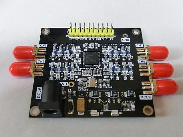
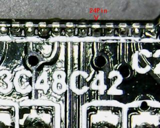
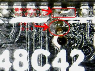
| 4.最初に手配したボードの不思議 |
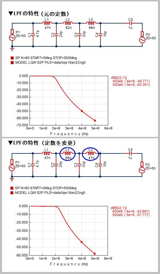
| 5.大きい方のボードの周波数特性 |
| 9.その他気づいたこと |
| 99.追記用 |
大幅な改定・追記用